One-Point Perspective: Lines Straight Back Meet at One Dot
TL;DR: Every edge that runs straight back, at right angles to the picture, aims at one dot at your eye level. That rule is one-point perspective: edges that face you stay level or upright, and a second dot, as far from the first as your eye is from the picture, sets how deep a square looks.
Rule: Every edge running straight away from you aims at one dot at eye level.
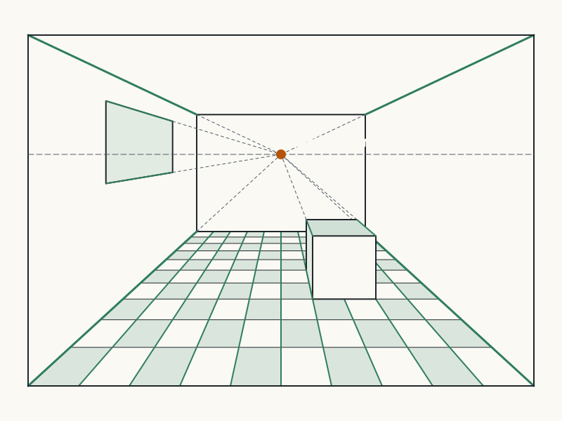
Narrow screen? Scroll the drawing sideways, or open it full size.
Full credit to copy
"A room in one-point perspective" by Drawn Mathematics, https://drawnmathematics.com/perspective/one-point-perspective/, licensed under CC BY 4.0, https://creativecommons.org/licenses/by/4.0/
Steps 1–2: the horizon and one dot
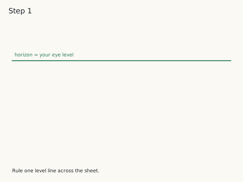
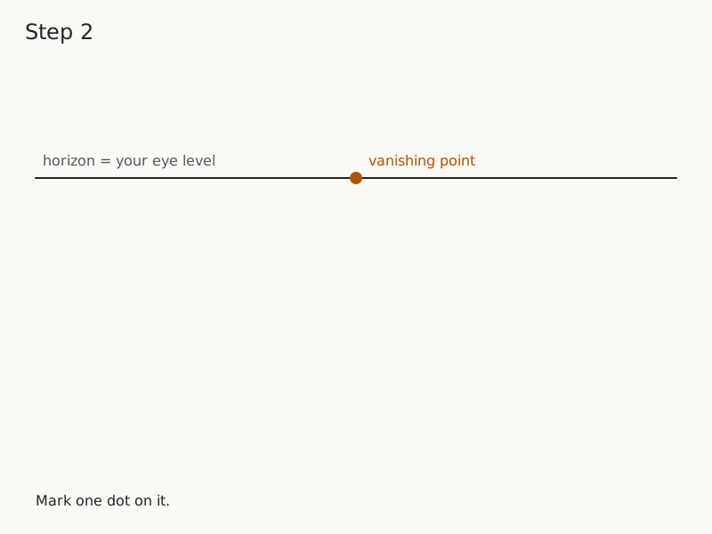
Think of the picture as an upright sheet of glass with the room traced on it. The horizon is the level line on that glass at the height of your eye. On that line, straight in front of your eye, sits the vanishing point. Leon Battista Alberti set up a painting the same way in De pictura (1435): he began with a rectangle that served him "pro aperta finestra", as an open window, and marked a single "centricus punctus", a centric point.
- Rule a level line across the sheet: the horizon, which stands for your eye level.
Narrow screen? Scroll the drawing sideways, or open it full size.
Full credit to copy
"Step 1: the horizon" by Drawn Mathematics, https://drawnmathematics.com/perspective/one-point-perspective/, licensed under CC BY 4.0, https://creativecommons.org/licenses/by/4.0/
- Mark one dot on it: the vanishing point.
Narrow screen? Scroll the drawing sideways, or open it full size.
Full credit to copy
"Step 2: the vanishing point" by Drawn Mathematics, https://drawnmathematics.com/perspective/one-point-perspective/, licensed under CC BY 4.0, https://creativecommons.org/licenses/by/4.0/
Where you put the dot is where you put the viewer. A box drawn below the horizon shows its top; one drawn above it shows its underside. Alberti placed his centric point no higher above the bottom of the picture than the height of the people he meant to paint, so that viewers and painted things seem to stand on one floor. He pointed to churches, where the heads of people walking about stay at about one height while the feet of those farther away come up to about the knees of those nearer.
Why the lines meet at one dot
Narrow screen? Scroll the drawing sideways, or open it full size.
Full credit to copy
"Why edges going back meet at one point, seen from above" by Drawn Mathematics, https://drawnmathematics.com/perspective/one-point-perspective/, licensed under CC BY 4.0, https://creativecommons.org/licenses/by/4.0/
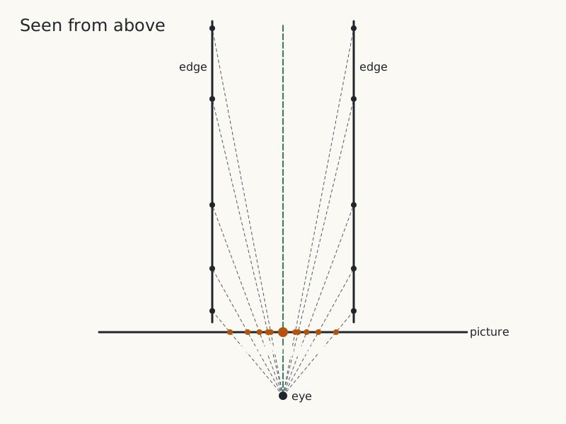
Look down on the scene from above. Two edges run straight back, side by side. The farther along an edge a point lies, the closer the line from your eye to that point comes to pointing straight ahead. So it crosses the picture closer to the spot in front of your eye, and the crossings from both edges crowd toward that one spot.
Put your eye at the origin and the picture d units in front of it. A point X units to the side, Y units up and Z units ahead then lands on the picture at (d × X ÷ Z, d × Y ÷ Z). Along an edge that runs straight back, X and Y stay fixed while Z grows, so both numbers shrink toward 0. Every such edge, wherever it starts, heads for the same spot, (0, 0): the vanishing point.
An edge that faces you keeps the same Z all along, so its picture is just the edge scaled by d ÷ Z. Level edges stay level and upright edges stay upright, which is why the front of the box in step 3 is an ordinary rectangle.
The whole construction assumes one eye at one spot. Move your eye and the match breaks, which is the idea behind Anamorphic Art: The Smear in The Ambassadors Is a Skull.
Steps 3–5: a box that recedes
- Draw the face of a box that faces you: a square with level and upright sides. Put it below the horizon and to the right of the dot.
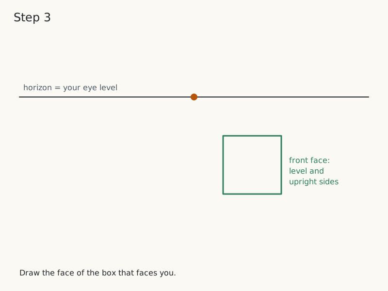
Narrow screen? Scroll the drawing sideways, or open it full size.
Full credit to copy
"Step 3: the front face of a box" by Drawn Mathematics, https://drawnmathematics.com/perspective/one-point-perspective/, licensed under CC BY 4.0, https://creativecommons.org/licenses/by/4.0/
- Join each corner of the rectangle to the dot with a light ruled line.
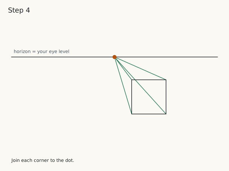
Narrow screen? Scroll the drawing sideways, or open it full size.
Full credit to copy
"Step 4: the edges that run straight back" by Drawn Mathematics, https://drawnmathematics.com/perspective/one-point-perspective/, licensed under CC BY 4.0, https://creativecommons.org/licenses/by/4.0/
- Draw the back face: a smaller rectangle with level and upright sides and its corners on those four lines. Erase the edges the box hides.
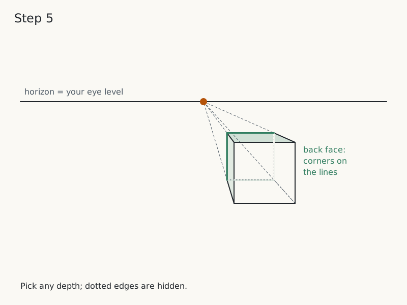
Narrow screen? Scroll the drawing sideways, or open it full size.
Full credit to copy
"Step 5: a box of chosen depth" by Drawn Mathematics, https://drawnmathematics.com/perspective/one-point-perspective/, licensed under CC BY 4.0, https://creativecommons.org/licenses/by/4.0/
The box sits below the horizon, so you see its top. It sits to the right of the dot, so you see its left side. Any depth you choose in step 5 gives a box, but not always the box you meant.
Steps 6–7: how deep is the box?
A cube needs a depth equal to its width. The four lines alone cannot give you that. The right depth depends on one more number: how far your eye is from the picture.
- Mark a second dot on the horizon, as far to the right of the vanishing point as your eye is from the picture, at the scale of your drawing. This is a distance point, 300 units out in the drawings here.
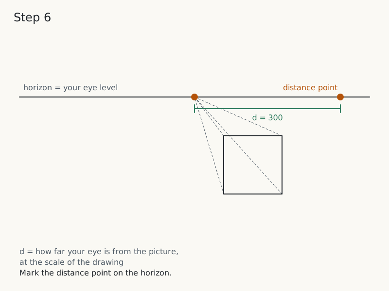
Narrow screen? Scroll the drawing sideways, or open it full size.
Full credit to copy
"Step 6: the distance point" by Drawn Mathematics, https://drawnmathematics.com/perspective/one-point-perspective/, licensed under CC BY 4.0, https://creativecommons.org/licenses/by/4.0/
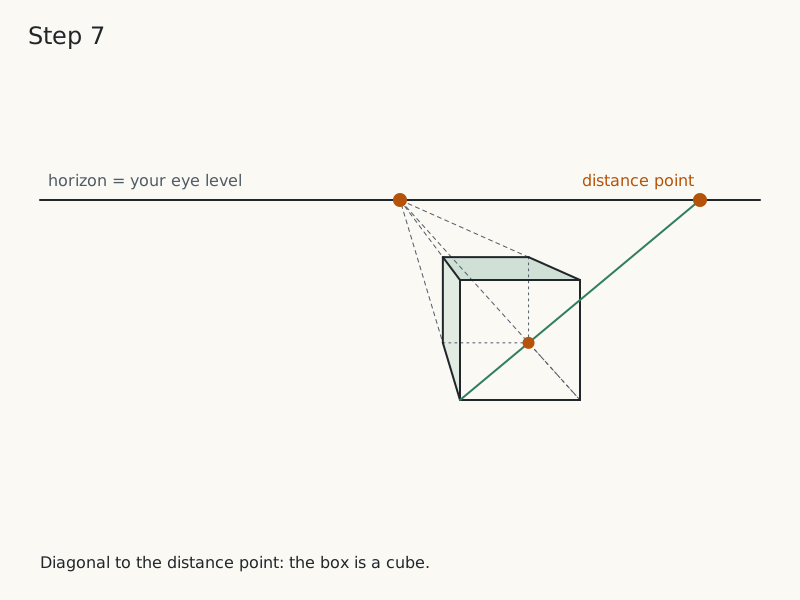
- Rule a line from the front bottom-left corner of the box to the distance point. Where it crosses the line from the front bottom-right corner, put the back corner of a square base, then finish the cube.
Narrow screen? Scroll the drawing sideways, or open it full size.
Full credit to copy
"Step 7: the depth of a cube from the distance point" by Drawn Mathematics, https://drawnmathematics.com/perspective/one-point-perspective/, licensed under CC BY 4.0, https://creativecommons.org/licenses/by/4.0/
The line in step 7 is the diagonal of the square base, which runs at 45° on the ground: one unit sideways for every unit back. Put that into the formula and its picture heads for (d, 0), on the horizon d units to the right of the vanishing point: the distance point. Move the distance point out to 450 units and the same base comes out shallower on the page, about 42 units deep instead of about 57. Alberti also tied his floor rows to a chosen distance between the viewer's eye and the picture, worked out in a separate small drawing.
Steps 8–10: tile the floor
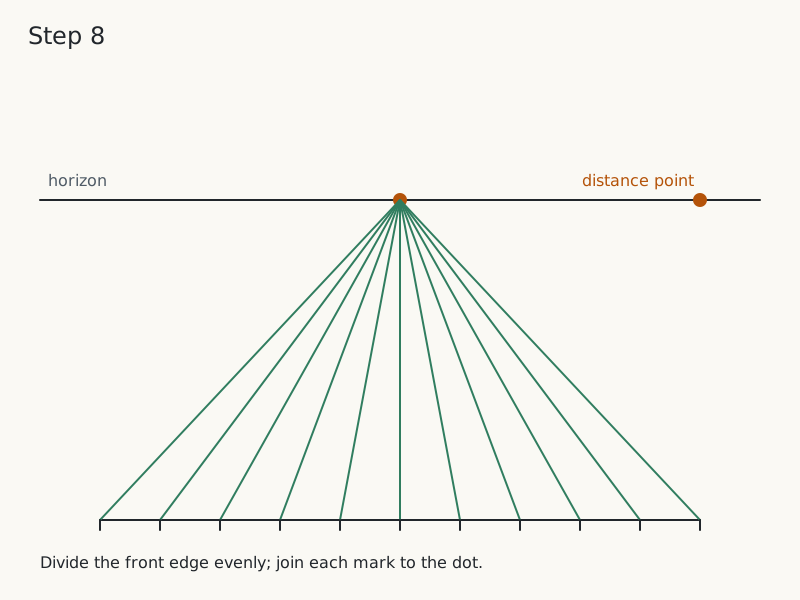
- Divide the front edge of the floor into equal tile widths, and join each mark to the vanishing point.
Narrow screen? Scroll the drawing sideways, or open it full size.
Full credit to copy
"Step 8: tile lines running back" by Drawn Mathematics, https://drawnmathematics.com/perspective/one-point-perspective/, licensed under CC BY 4.0, https://creativecommons.org/licenses/by/4.0/
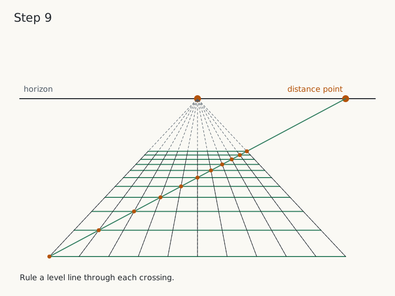
- Rule one diagonal from the left end of the front edge to the distance point. Through each place where it crosses a line from step 8, rule a level line; these are the rows of square tiles.
Narrow screen? Scroll the drawing sideways, or open it full size.
Full credit to copy
"Step 9: rows of square tiles from one diagonal" by Drawn Mathematics, https://drawnmathematics.com/perspective/one-point-perspective/, licensed under CC BY 4.0, https://creativecommons.org/licenses/by/4.0/
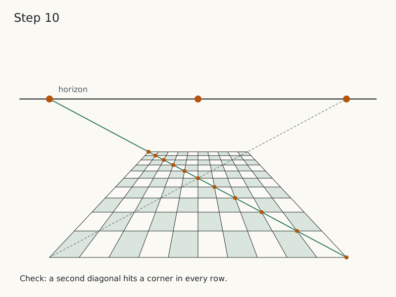
- Shade every other tile. Then check: a second diagonal, from the right end of the front edge to a distance point the same distance to the left, must pass through a tile corner in every row.
Narrow screen? Scroll the drawing sideways, or open it full size.
Full credit to copy
"Step 10: the diagonal check" by Drawn Mathematics, https://drawnmathematics.com/perspective/one-point-perspective/, licensed under CC BY 4.0, https://creativecommons.org/licenses/by/4.0/
Step 10 is Alberti's own test:
"Qui quidem quam recte descripti sint inditio erit, si una eademque recta continuata linea in picto pavimento coadiunctorum quadrangulorum diameter sit." (Leon Battista Alberti, De pictura, Book I, 1435; Latin text edited by Cecil Grayson, 1973)
The rows are right, he wrote, if one continuous straight line runs as the diagonal of a chain of joined squares on the painted floor. He also rejected a shortcut that set each new row back by a fixed fraction of the gap before it, because its first row was placed by chance and its result had no fixed spot for the eye.
A common construction mistake is to space the rows evenly. The rows then stay equally deep on the page as they go back, and the corners that should line up along a diagonal bend away from a straight line.
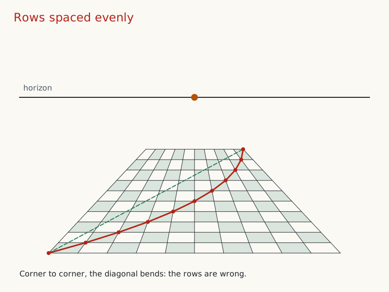
Narrow screen? Scroll the drawing sideways, or open it full size.
Full credit to copy
"A common mistake: rows spaced evenly" by Drawn Mathematics, https://drawnmathematics.com/perspective/one-point-perspective/, licensed under CC BY 4.0, https://creativecommons.org/licenses/by/4.0/
| Step | Do this | You get |
|---|---|---|
| 1 | Rule a level line across the sheet | The horizon, at eye level |
| 2 | Mark one dot on it | The vanishing point |
| 3 | Draw a square with level and upright sides | The face of a box that faces you |
| 4 | Join each corner to the dot | The edges that run straight back |
| 5 | Draw a smaller rectangle with its corners on those lines | A box of any depth |
| 6 | Mark a dot on the horizon, your viewing distance from the first | The distance point |
| 7 | Rule from a front corner to the distance point | The depth of a cube |
| 8 | Divide the front edge evenly and join each mark to the dot | The tile lines running back |
| 9 | Rule a diagonal to the distance point; rule level lines through the crossings | Rows of square tiles |
| 10 | Rule the other diagonal | A check: one corner in every row |
Check it on a painting
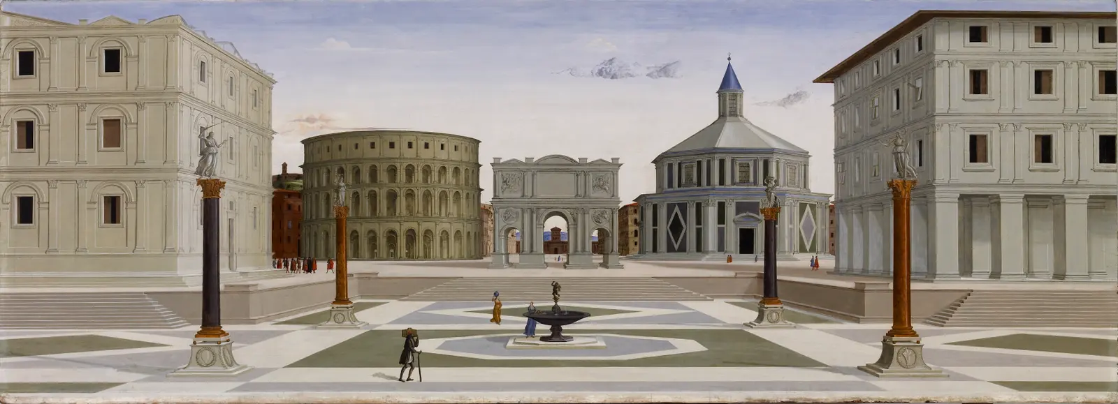
The Ideal City is a panel in oil and tempera, 220 cm wide, from about 1480–1484, now in the Walters Art Museum (37.677). The museum's record credits a Florentine artist and Giuliano da Sangallo (about 1443–1516).
Full credit to copy
"The Ideal City" by an unnamed Florentine artist and Giuliano da Sangallo — https://commons.wikimedia.org/wiki/File:Fra_Carnevale_-_The_Ideal_City_-_Walters_37677.jpg — Public domain (Painted about 1480–1484; credited by the Walters Art Museum to an unnamed Florentine artist and Giuliano da Sangallo (d. 1516), and an artist at work in the 1480s cannot have lived past 1956; PD worldwide (US: published before 1930; EU: authors died more than 70 years ago); museum photograph of a two-dimensional work released as public domain by the Walters Art Museum (Commons Walters Art Museum licence, VRTS ticket 2012021710000834))
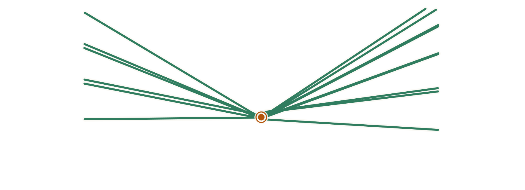
The overlay below assumes what this article assumes: one vanishing point for every edge that runs straight back, on a flat panel. Its lines come from the side faces of the two palaces, whose fronts are painted with level edges, so those side faces should run straight back. Before any fitting, a tolerance of 1% of the image width was written down, with a rule: every straight edge there at least 100 pixels long, with both ends clearly visible, goes in. Fifteen edges qualify (roof and cornice edges, string courses, the foot of the right-hand arcade).
Each edge was located on the museum's 1,798 × 651 pixel scan and extended. The fitted point is the one with the smallest sum of squared distances to all 15 lines.
Full credit to copy
"Overlay: the receding edges of The Ideal City and their best-fit vanishing point" by Drawn Mathematics, https://drawnmathematics.com/perspective/one-point-perspective/, licensed under CC BY 4.0, https://creativecommons.org/licenses/by/4.0/. The license covers the overlay only. Base image: "The Ideal City" by an unnamed Florentine artist and Giuliano da Sangallo — https://commons.wikimedia.org/wiki/File:Fra_Carnevale_-_The_Ideal_City_-_Walters_37677.jpg — Public domain (Painted about 1480–1484; credited by the Walters Art Museum to an unnamed Florentine artist and Giuliano da Sangallo (d. 1516), and an artist at work in the 1480s cannot have lived past 1956; PD worldwide (US: published before 1930; EU: authors died more than 70 years ago); museum photograph of a two-dimensional work released as public domain by the Walters Art Museum (Commons Walters Art Museum licence, VRTS ticket 2012021710000834)); modified: computed vanishing lines and best-fit point overlaid; the painting is not altered.
What the overlay finds
All 15 lines pass within 16.2 pixels of that point, 0.9% of the width and inside the tolerance. The typical miss (root mean square) is about 7 pixels, or 0.4%. On the panel itself, the largest miss comes to about 2 cm. The lines, the point and every distance are in one-point-perspective-ideal-city-lines.csv (CSV; where this file comes from: source, version and license, JSON) Source data: Measured for this page on the Walters Art Museum's public-domain scan of The Ideal City (37.677), 1798 × 651 px.
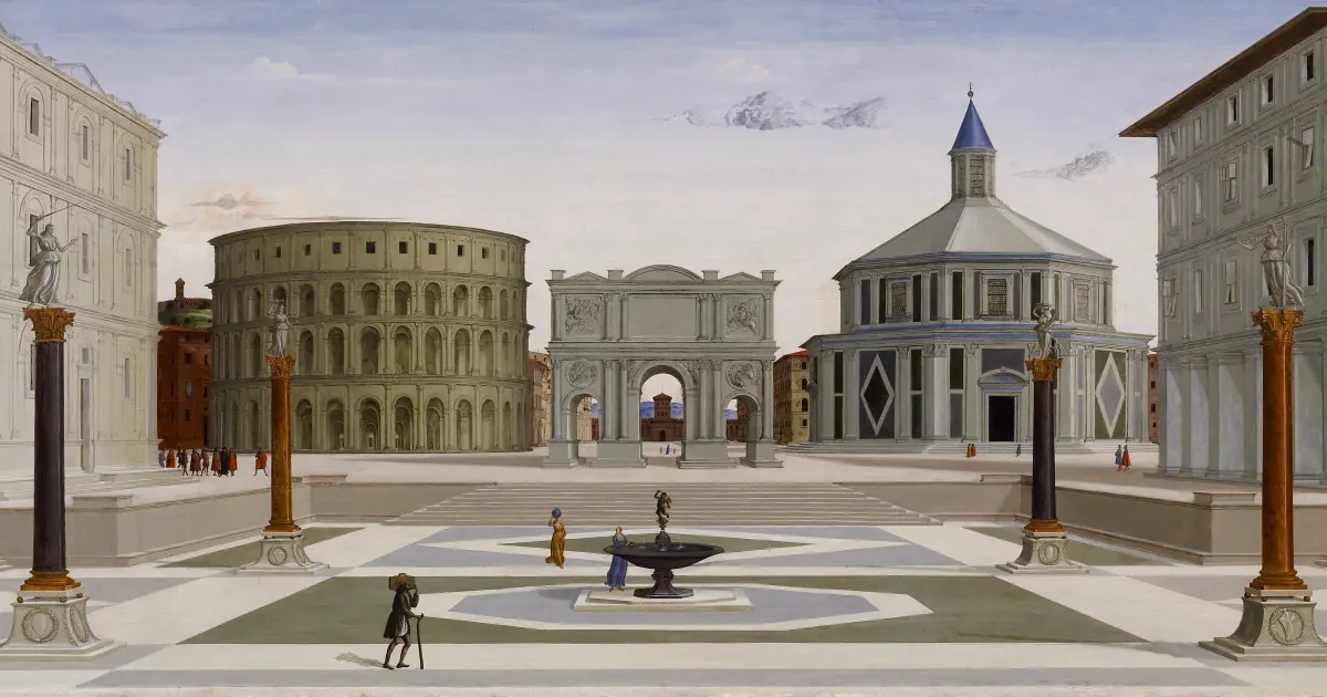
The point sits 4 pixels left of the scan's center line and 38% of the way up from its bottom edge. It falls at the small doorway of the far building framed by the central arch.
Full credit to copy
"The Ideal City (central part)" by an unnamed Florentine artist and Giuliano da Sangallo — https://commons.wikimedia.org/wiki/File:Fra_Carnevale_-_The_Ideal_City_-_Walters_37677.jpg — Public domain (Painted about 1480–1484; credited by the Walters Art Museum to an unnamed Florentine artist and Giuliano da Sangallo (d. 1516), and an artist at work in the 1480s cannot have lived past 1956; PD worldwide (US: published before 1930; EU: authors died more than 70 years ago); museum photograph of a two-dimensional work released as public domain by the Walters Art Museum (Commons Walters Art Museum licence, VRTS ticket 2012021710000834)); modified: cropped to the central 1200 × 630 px (x 295–1495, y 10–640 of the 1798 × 651 px file); not scaled; colours not altered
Three things could bend these numbers: the lens and framing of the museum photograph, warping in the wooden panel, and later restoration. None of them was measured, but four level edges on the palace fronts lie within 0.4° of the scan's horizontal.
The two largest misses, about 15 and 16 pixels, both sit on the cornice above the right-hand arcade, close to the 18-pixel tolerance. A first trial fit used one edge of each band on the right-hand palace and two edges read partly across a statue or column in front of them. It put this cornice's upper edge just outside the tolerance, by less than a hundredth of a pixel, and the CSV keeps that result. With those two readings corrected, the same 12 edges all pass inside.
That the painter ruled every one of these edges to one point, and that the spread comes from painting over the ruled lines, is this site's interpretive hypothesis, not something the overlay proves. The site's rules for painting overlays are on the checking page.
A printed plate can leave the construction in view. In plate 10 of the second part of Hans Vredeman de Vries's Perspective, etched by Bartholomeus Willemsz. Dolendo after his design, dotted lines run back toward one point on a dotted horizon line that the plate labels "Orison".
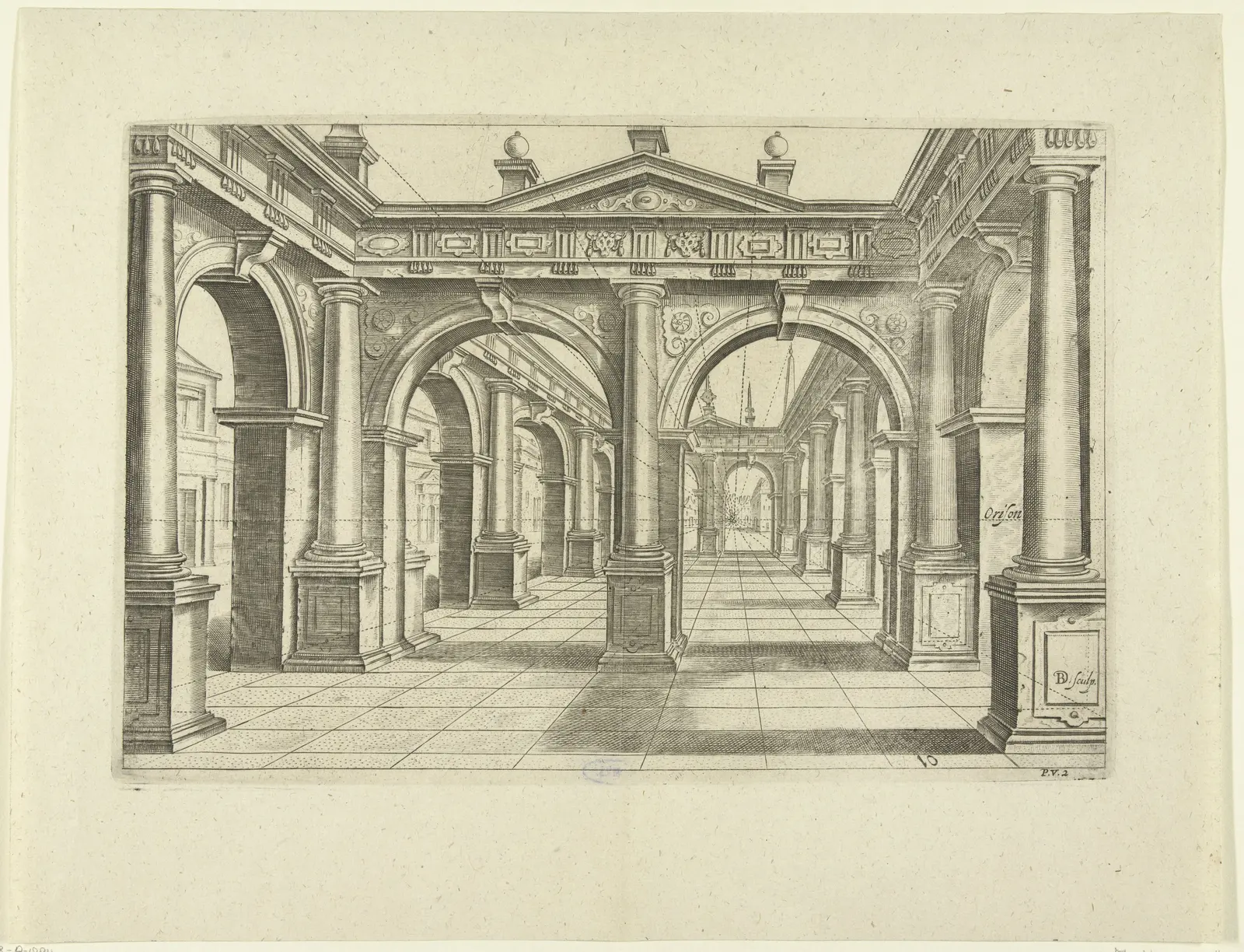
Full credit to copy
"Gebouw met dubbele boog in het midden in Dorische stijl (Perspective, deel 2, no. 10)" by Bartholomeus Willemsz. Dolendo, after Hans Vredeman de Vries — https://commons.wikimedia.org/wiki/File:Gebouw_met_dubbele_boog_in_het_midden_in_Dorische_stijl_Perspective,_deel_2_(serietitel),_RP-P-1878-A-1884.jpg — Public domain (Etching by Bartholomeus Willemsz. Dolendo after a design by Hans Vredeman de Vries (1527–about 1604, Library of Congress name authority), dated 1581–1629 by the Rijksmuseum, so no maker lived past 1956; PD worldwide (US: published before 1930; EU: authors died more than 70 years ago); museum image released under CC0 by the Rijksmuseum (RP-P-1878-A-1884))
When one dot is not enough
One dot handles only edges that run straight back. Turn a box on the floor so that none of its edges does, and its level edges aim at two dots on the horizon instead, one on each side, while its upright edges stay upright. That is two-point perspective. The dot straight in front of you is still the vanishing point for any edge that runs straight back; the turned box just has no such edge.
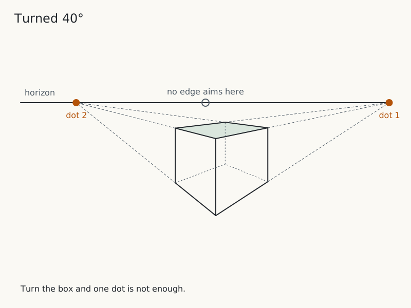
Narrow screen? Scroll the drawing sideways, or open it full size.
Full credit to copy
"A turned box needs two vanishing points" by Drawn Mathematics, https://drawnmathematics.com/perspective/one-point-perspective/, licensed under CC BY 4.0, https://creativecommons.org/licenses/by/4.0/
The formula says where the two dots go. With d = 300, an edge turned 40° away from straight back heads for a point d × tan 40° ≈ 252 units to one side, and the edges at right angles to it head for d ÷ tan 40° ≈ 358 units to the other. Only edges parallel to the picture keep their direction. Tip the picture up or down, as when you look up at a tower, and upright edges stop being parallel to it, so they run toward a third dot.
Draw it yourself:
With paper and a few simple tools
- Rule a level line a third of the way down an A4 sheet: that is the horizon.
- Mark one dot on it, near the middle.
- Draw a rectangle below the line, with level and upright sides.
- Join each corner of the rectangle to the dot with light lines.
- Draw a smaller rectangle with sides parallel to the first and its corners on those lines, then erase the hidden edges.
Next: Test the same rule on a Vermeer: Vermeer's Milkmaid: 11 Traced Edges Aim Just Above Her Hand · A chessboard floor is a pattern that repeats in two directions, seen at a slant: Wallpaper Groups: Only 17 Symmetry Types for Two-Way Repeats
Sources
- [1] Leon Battista Alberti, De pictura (1435), Book I, sections 19–20; Latin text from Opere volgari, vol. 3, ed. Cecil Grayson (Bari: Laterza, 1973), as transcribed on Latin Wikisource. https://la.wikisource.org/wiki/De_pictura/Liber_I Read: full text of Book I, sections 19–20, in Latin; one sentence quoted, the rest paraphrased. Text license: CC BY-SA 4.0.
- [2] Original data for this page: exact central projections behind every drawing (method in the text) and the 15 receding edges measured on the Walters scan of The Ideal City, with their best-fit point (CSV download). https://drawnmathematics.com/perspective/one-point-perspective/one-point-perspective-ideal-city-lines.csv Read: this page's own computation; method in the text, measured lines in the CSV download.
- [3] Walters Art Museum, The Ideal City, accession number 37.677, collection data files art.csv and creators.csv, published by the museum on GitHub. https://github.com/WaltersArtMuseum/api-thewalters-org/blob/main/art.csv Read: collection record (key facts).
- [4] Rijksmuseum, Gebouw met dubbele boog in het midden in Dorische stijl (Perspective, deel 2, no. 10), object number RP-P-1878-A-1884, collection record. https://id.rijksmuseum.nl/200427154 Read: collection record (key facts).
Cite this page
Drawn Mathematics. “One-Point Perspective: Lines Straight Back Meet at One Dot.” Drawn Mathematics. Published 2026-10-26. https://drawnmathematics.com/perspective/one-point-perspective/ (accessed: add the date you read it).
How each drawing is checked: Checking the constructionCorrections and redrawsHow to reach us